At t=0 the drum is at its maximum negative vertical displacement. It looks like a bowl, and curves smoothly to the sides of the circular drum head, which are fixed at z=0. Since the drum reaches its maximum positive displacement 0.2 seconds later, at t=0.1 seconds the drum head is half way between its minimum and maximum. Thus the drum would be perfectly flat. At t=0.2 seconds the drum has reached its maximum positive vertical displacement so that the it would look like an upside down bowl, much like an inversion of the drum head at t=0 seconds.
The drum, over time, will oscillate between the states described (and illustrated) in part 1.
- The drum head at t=0, with x=0.
This cross-section is the profile of the drum head along the y axis at t=0 , and would look the graph below.
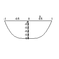
- How do these cross-sections change in time?
In time, the cross-section would flatten, and then bulge upward. As t increases beyond t=0.2 seconds the bulge will flatten, depress and oscillate back and fourth.
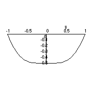
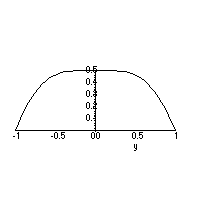
- The center of the drum (x=0, and y=0).
At x=0, y=0, we are looking at the height of the center of the drum head over time. From part 1 the drum head starts at it's maximum negative vertical displacement, at t=0.1 seconds the drum head is flat, and at t=0.2 seconds the drum head has reached it's maximum positive vertical displacement. This trend will continue, at t=0.3 seconds the drum head will be flat, and at t=0.4 the drum head will be back where it started at a maximum negative vertical displacement. Thus the center oscillates from -0.5 inches to 0.5 inches with a period of 0.4 seconds, so it would look like
 , which is shown below.
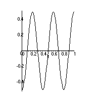
- How does this cross section change as x is increased to x=1.
A cross-section with
 and
and  fixed looks at how the
displacement changes in time at the point
  . As we consider
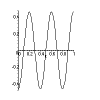
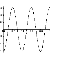
points closer to the edge of the drum (x=0) the amplitude should decrease.
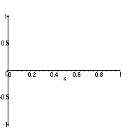
The point (1,0) is fixed at z=0, thus the amplitude should be zero at (1,0). The cross-sections for the points (0.25,0), (0.5,0), (0.75,0),
and (1,0) are drawn below.
-
From looking at the surface in 1, it is clear that the function z=f(x,y,t)
should have circular symmetry in x and y (i.e.
 is the only
way x and y appear in the function.)
We already know that z=f(x,y,t) should oscillate in time like ![]() (see part 3c,d) the remaining part is to describe the
amplitude as a function of x and y. This should have circular symmetry
with a maximum amplitude at (0,0) and should decrease to zero amplitude at
the drums edge (
(see part 3c,d) the remaining part is to describe the
amplitude as a function of x and y. This should have circular symmetry
with a maximum amplitude at (0,0) and should decrease to zero amplitude at
the drums edge ( ![]() ). The maximum displacement is 0.5 inches
and the function should start at the maximum negative displacement. Two such
functions are:
). The maximum displacement is 0.5 inches
and the function should start at the maximum negative displacement. Two such
functions are:
![]()
and
![]()
Where x and y are measured in feet and the resulting amplitude is measured in inches. So the corresponding functions to describe the motion of the drum head would be:
![]()
and
![]()
- Fix t=0
- Fix t=0.05
- Fix t=0.1
- Fix t=0.2
- Do your contour diagrams agree with your descriptions in part 1?
One way is to include an exponential (in time) damping term in the
amplitude: ![]() . The first function would become
. The first function would become
![]()
and the cross section for the middle of the drum (x=0 and y=0) would be
